
iceQ SmartBox V3 & V4
SUMMARY
The following installation guide will provide you with the necessary information to successfully install iceQ 3.0 into your Ice Merchandisers.
01
What you should have received with your iceQ purchase
05
How to connect the iceQ controller

02
Installing the Sensor Array
06
How to check everything out before leaving the site
UPON RECEIVING YOUR ICEQ 2.0, CALL ME AT 925.984.9371 TO SCHEDULE YOUR ONBOARDING CALL
07
Tools Required
How to Drill the Exit Hole
03
Securing the Sensor Array Cable
04
01 - What you should have received with your iceQ purchase
Sensor array — Goes inside the freezer, mounted at the front with magnets (contains 2 to 4 sensors depending on size).
Controller — The iceQ Controller that connects to the freezer power and the Sensor array; collects and sends data to the iceQ system.
Power Supply — A 12-volt power supply that provides power to the Sensor array and the Controller.
Y-Adapter — Mounts easily and directly into the Leer light wiring; can also be used on non-Leer freezers.
Main cable — Connecting power, controller, and sensor array
Misc Parts — Cable grommets, wire-ties, screws, and coax seal for waterproofing the connection between the main cable and power supply.
UPON RECEIVING YOUR ICEQ 2.0, CALL ME AT 925.984.9371 TO SCHEDULE YOUR ONBOARDING CALL
Install Video
iceQ install V3 and V4
02 - Installing the Sensor Array

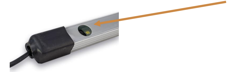
The Sensor array is the first thing you setup. Take the bubble wrap off and uncoil the cable. Check each sensor to make sure the plastic cover has not shifted and or remove any debris. It should look like this:
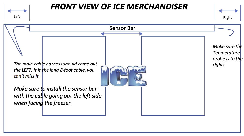
Next, mount the Sensor array on the front of the freezer centered left to right. Just make sure the distance on each side is the same. Measure each side and slide the Sensor array (left to right), until the Sensor array end is the same distance to the edge of the freezer as shown in the diagram below.
Make sure to mount the sensor array with the long (main cable) to the left and the temperature probe on the right.
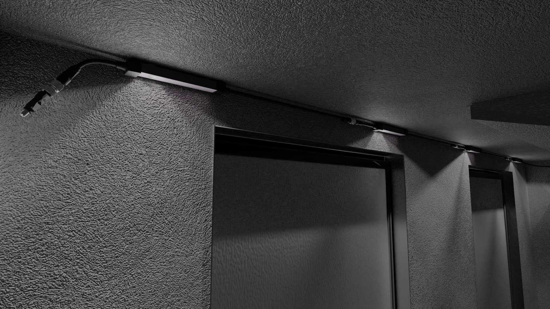
Here is picture of what your Sensor array should look like from the inside of a freezer. Note, the lights are on. When you first install the Sensor array, the lights will not come on until you connect the controller to the power supply, but we’ll get to that next! It is important to make sure the Sensor array is up against the front of the freezer, so it does not get damaged or knocked off. By placing it up against the front of the freezer as shown below, it will not interfere with drivers stuffing the freezers or customers pulling bags of ice out. If there’s a light fixture already installed and there’s not enough room to mount the Sensor array, remove the light fixture! We got LED lights that won’t burn out.
03 - Drill Exit hole for Sensor array Cable
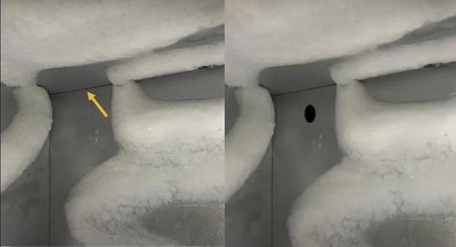
CAUTION: MAKE SURE TO TURN ON THE FREEZER TO SEE WHERE THE FROST LINES ARE AND AVOID THEM AT ALL COSTS! IF YOU SCREW THROUGH A COIL THE MERCHANDISER WILL BE RUINED.
For Cold Wall and even for Auto-Defrost Ice Merchandisers, drill a one-inch hole out in an area where no coils are present at the back as pictured above.
Auto-Defrost Pro Tip: Many of our customers that have Auto-Defrost Freezers, just feed the cable through the evaporator and no drilling is required. Either approach will work.
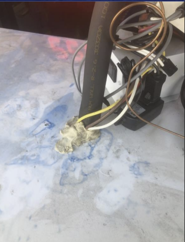
Make sure to use the gromets provided and then use Plumber's putty to plug the hole. Also, the Sensor array Cable is equipped with a dust-cover, to protect it from getting debris and other material. Make sure to leave this on until you connect the cable to the iceQ Controller.
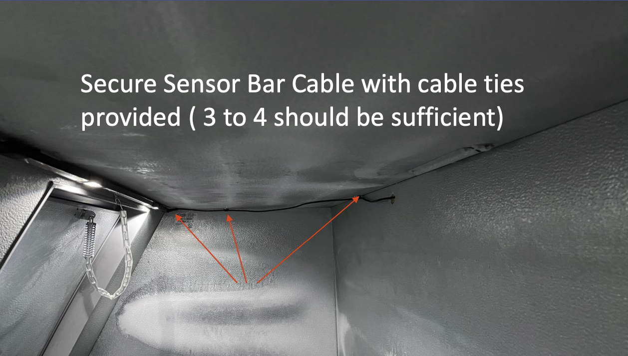
04 - Securing the Sensor array Cable
Attaching cable with wiretie.
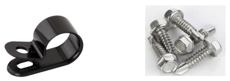
Using the cable clamps provided and the self-screwing screws, secure the cable as shown in the picture, making sure to not drill into a coil! (applies to Cold wall Freezers, Auto-Defrost Freezers, you can drill anywhere!
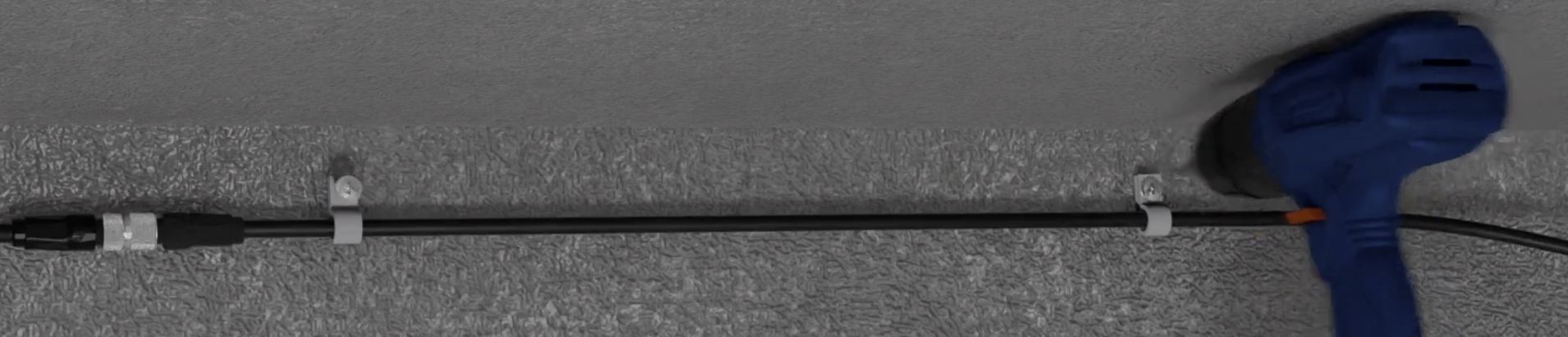
Screwing the wiretie. Be Extra careful to not hit the coil in cold walls.
MAKE SURE TO TURN ON THE FREEZER TO SEE WHERE THE FROST LINES ARE AND AVOID THEM AT ALL COSTS WHEN DRILLING OR SCREWING! The seams and the corners are your best bet.
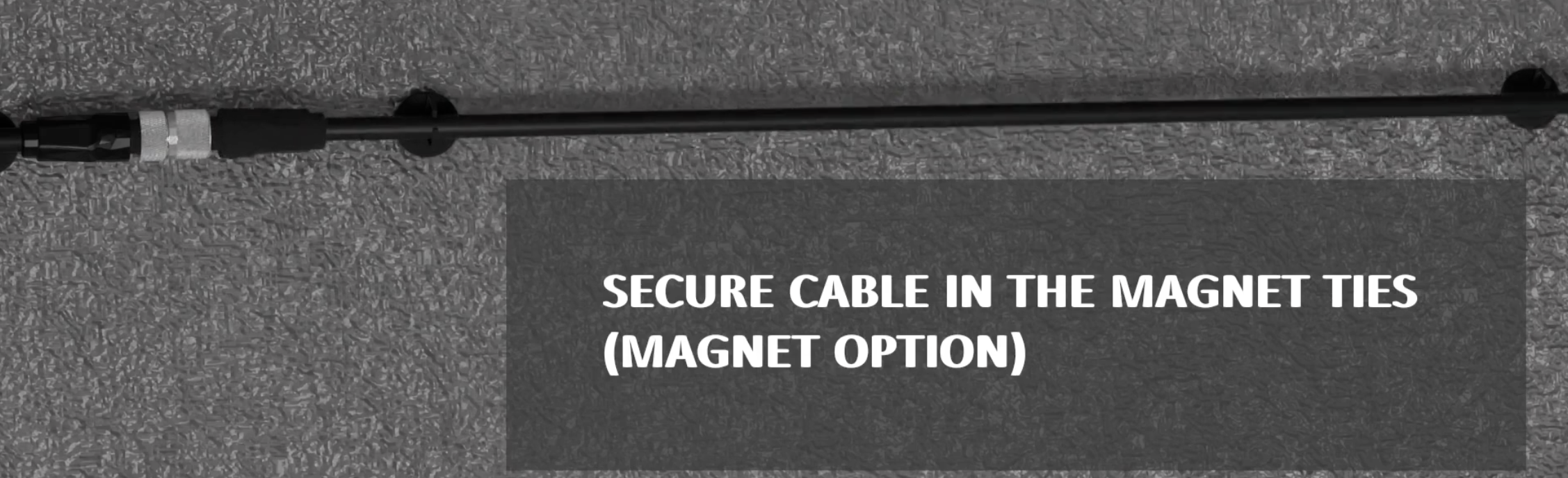
Attaching cable with Magnets (Cold wall kit - sold separately).
05 - Installing the iceQ Controller
Once you have fed the main Sensor array Cable all the way through the Exit Hole, you are ready to connect the iceQ Controller.
There are three basic steps to connecting the controller:
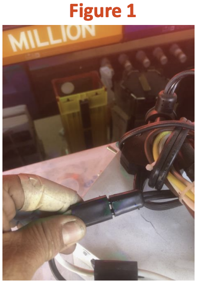
Connect the Y-Adapter to the Light fixture adapter as shown in figure 1. (note this comes standard on all Leer Merchandisers. If missing, you the Y-Adapter to hard wire into the freezer power).
Connect the Power Supply to the Y-Adapter and to the power connector on the main Sensor Cable as show in Figure 2. Be sure to use the sticky tape to seal the power connection as shown in Figure 3.
Connect the main Sensor array Cable to the Controller and tuck all the excess wires using the wire ties provided.
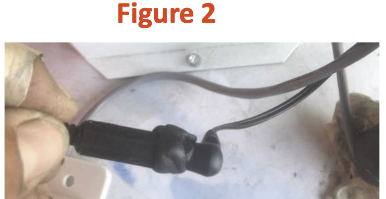

Figure 3
06 - Validate that the install was successful
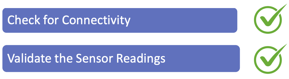
Testing for connectivity is easy super easy! If you see a flashing green light on the controller after connecting the power, you are good.
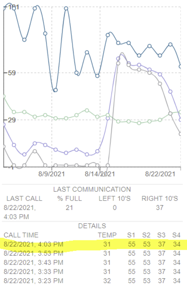
Also, if can see the readings on the iceQ mobile site, you have connectivity!
Validate that you installed everything correctly, by opening both doors of the freezer and leave them open. Next, power cycle the controller by unplugging the power source. After about 60 seconds, refresh the readings shown on the right , and make sure the inches correspond to the actual distance per sensor. A good eye or tape measure does the trick!
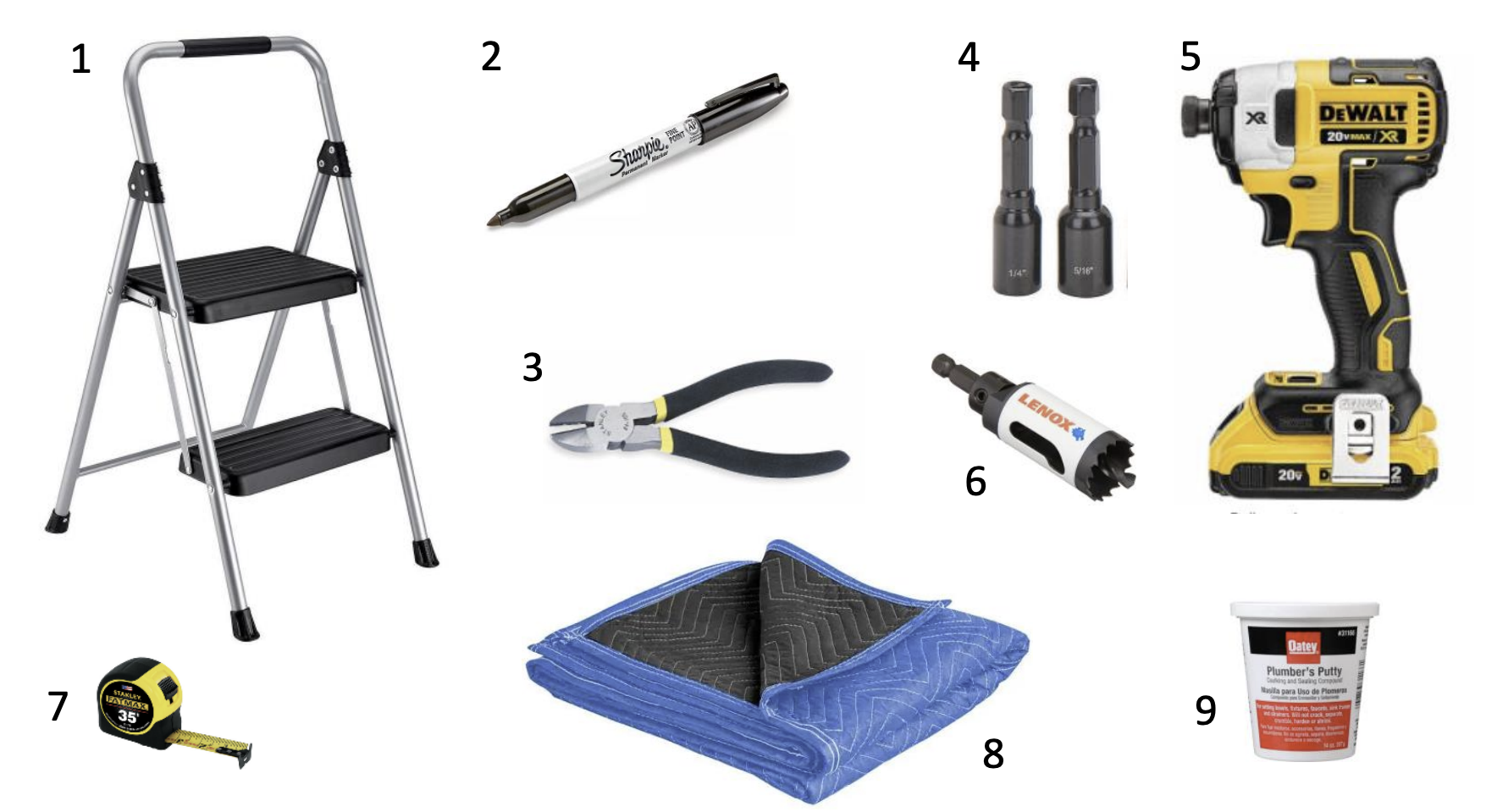
07 - Tools Required
Step Chair or ladder to Get onto of the freezer!
Black Sharpie to Mark exist hole
Wire Cutters to Cut off wire ties and cut wires
¼ and ½ bit drivers To remove the cowling
Impact Drill Driver to remove cowling and drill exit hole.
1 inch hole driver to drill one exit hole
Shipping Blanket to protect ice if doing a field install
Tape Measure: You kidding me!
Plumbers Putty to seal the hole you make